Blog 13
Computer Drawing:
Phase 1:

Phase 2:

Schematic:

Explanation:
One side of the first relay runs the motor atop phase 1 which powers the car to be pulled up the incline which eventually covers the photo resistor. This flips the relay to the other side which power the motor of phase 2. This causes the lift to go upward therefore, uncovering photo resistor 2 which then flips a sepperate relay to switch on powering the fan to blow a piece of paper uncovering Scout's photo resistor. Some issues I still have with my setup is that the time just barely reaches the 10 second minimum this is primarily due to when the left begins to lift up it uncovers the photo resistor beneath it so quickly that it almost instantaneously swithches the second relay. I want to make a more elaborate cover because if you look closely this was the failure in my second video. The fan starts running even before the lift begins to move because the second phtoto resistor was never covered properly. Although the above schematics look very similar it is important to note that the location of the photo resistors in relation to the op amp gives them the required functionality. The first one is used to increase the amplification when covered and the second one is used to increase the amplification when uncovered this is why they are in opposite possitions in relation to the op amp in the schematic.
Pictures:

Figure 1: shows incline of phase 1

Figure 2:Shows DC motot 1 at the top of phase 1

Figure 3: Shows phase 2

Figure 4: Shows phase 4 (the transition)

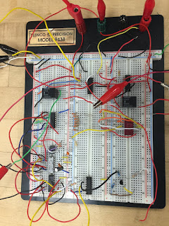
Figure 5: Circuit board
Videos:
Video 1: Sucessful Rube Goldberg
Video 2: Rube Goldberg failure
Failures:
The failure with the original circuit was primarily that I could not achieve pulling off the piece of paper with only 1 second of power so I eliminated the clock from my circuit and added in the additional relay, opamp and motor. Another issue I had was for some reason I still have not been able to understand is that on the day of the individual demos my motor on the top of phase 1 kept getting weaker after each use. I decreased the incline to provide more room for error and have since had no issues with it.
Austin, all looks good. Your new schematic does not have the timer though. You had it in the previous drawing.
ReplyDeleteI really like the complexity of your different mechanical parts going, I was curious though if you were planning on using a whole sheet of paper to activate the photo resistor for the transition or just a smaller part covering it? Because it looks like the paper would need a relatively flat surface, however if scout's photo resistor is close to the circuit wires could end up dragging on the paper possibly not moving it properly.
ReplyDeleteI really like the idea behind your mechanical part of the circuit. You could probably try to use something lighter to cover up the photo cell like a small piece of cloth? This would also cover it more efficiently. I like how you adapted to the situation and added the additional relay, opamp and motor to make the circuit work.
ReplyDeletein my opinion your mechanical part is very good i like your idea from using the car to pull up the incline to make the photo sensor work. i think you are doing well
ReplyDeleteThe circuit hasn't changed much since last week. I think this is a good thing. The circuit is definitely very cool. I am glad you got your circuit situated better from last week. I hope all goes well!
ReplyDeleteAustin and Scout,
ReplyDeleteI really like your circuit design. I think the timers are great and I really like the mechanical design. I also like the paper covering the PS resistor, but my one concern is if the motor will be strong enough to lift the cart up the device. This is my concern because from my past experience with the tiny motors is that you need a lot of voltage to power them so they lift heavy object, but overall I really like the circuit and enjoyed watching Scout's timer power his motor from 4 to 9.